ProductSERVICE
CONTACT US
Hunan Perfect Industry Co.,Ltd
Contact: Manager Hu, Manager Yi
Hotline:008618507312158
Cell phone:008613974960765
Address:Xiangyin County Industrial Park, Yueyang City, Hunan Province, China
Current location: HOME »Product »Vertical suspended pumps
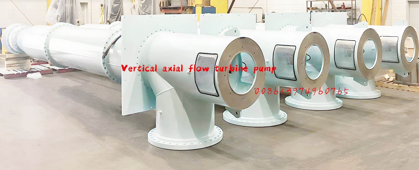
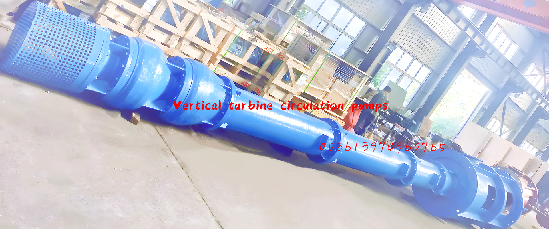
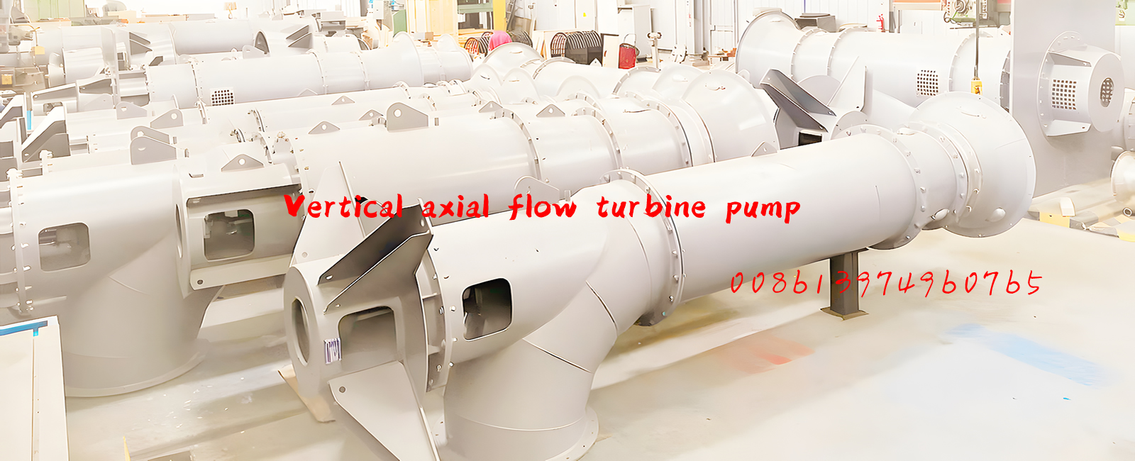
Vertical suspended axial flow pump
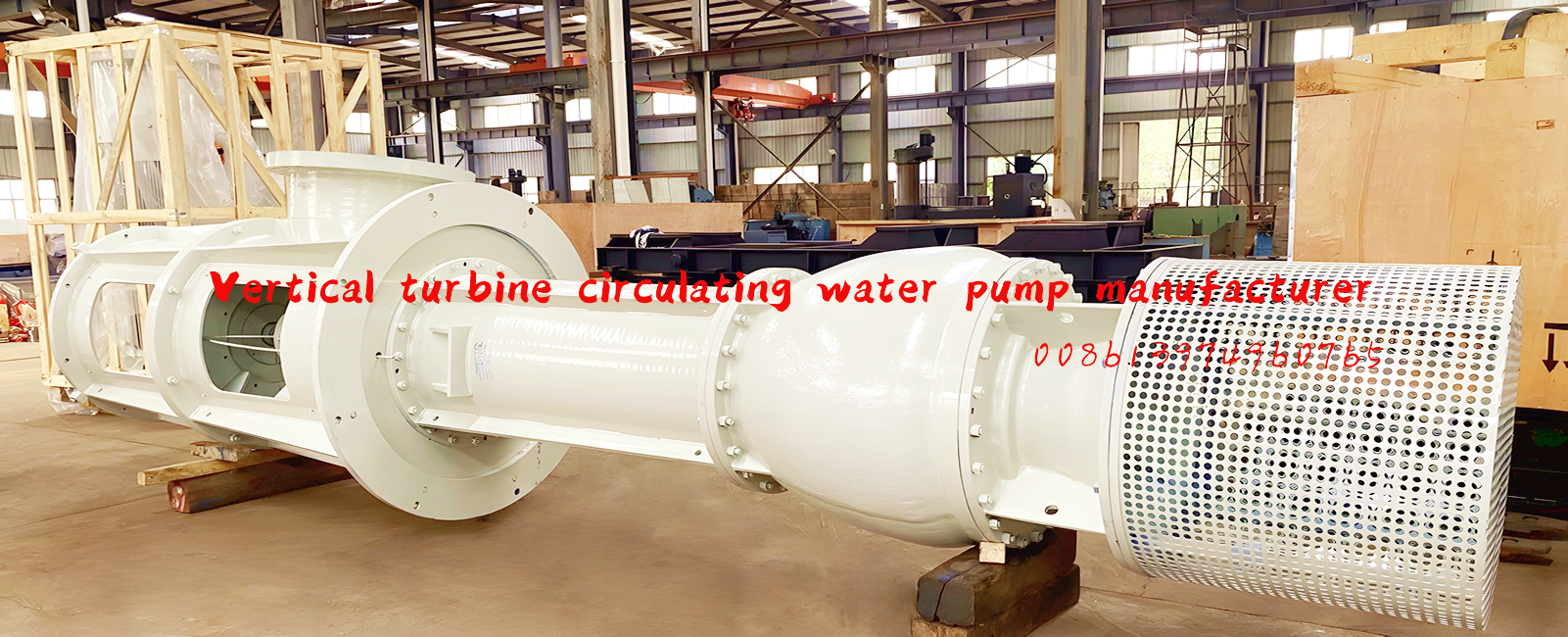
Vertical suspended axial flow pump: single-stage vertical axial flow pump. It is suitable for pumping clean water, sewage (or wastewater) and slightly corrosive liquids, and the temperature of the conveyed liquid is generally not higher than 50 °C. This type of pump is a large-flow, low-lift pump, which can be used for farmland drainage and irrigation, salt plant, aquaculture, water supply, drainage, sewage treatment, power plant transmission of circulating water, dock water level lifting or other water conservancy projects, and can also be used in metallurgy, chemical and other industries (special requirements can be designed separately), and is widely used.

Performance range
Flow rate Q = 0.18 ~ 50 m³/s
Head H = 1 ~ 22 m
Model description
1. Models with a diameter of 40 inches or less
Example: 14ZLB-3.6
14—Outlet diameter (in)
Z—axial flow pump
L—vertical
B—semi-adjusting blades
3.6-design head
2. Caliber 40 inches and above models
Example: 65ZLB-50
65—Outlet diameter (in)
Z—axial flow pump
L—vertical
B—Semi-adjusting blades (full adjustment is represented by Q)
50—The value obtained by dividing the specific speed by 10
There are 39 kinds of ZLB and ZLQ pump products, of which the diameter of 40 inches and above can be made into a full regulation (ZLQ) pump.
Structural features
This type of pump can be designed as a double-base vertical split structure and a single basic structure with direct connection between the motor and the pump.
1. Double-foundation vertical split structure
The pump is mainly composed of the pump body, transmission device, transmission shaft, etc.
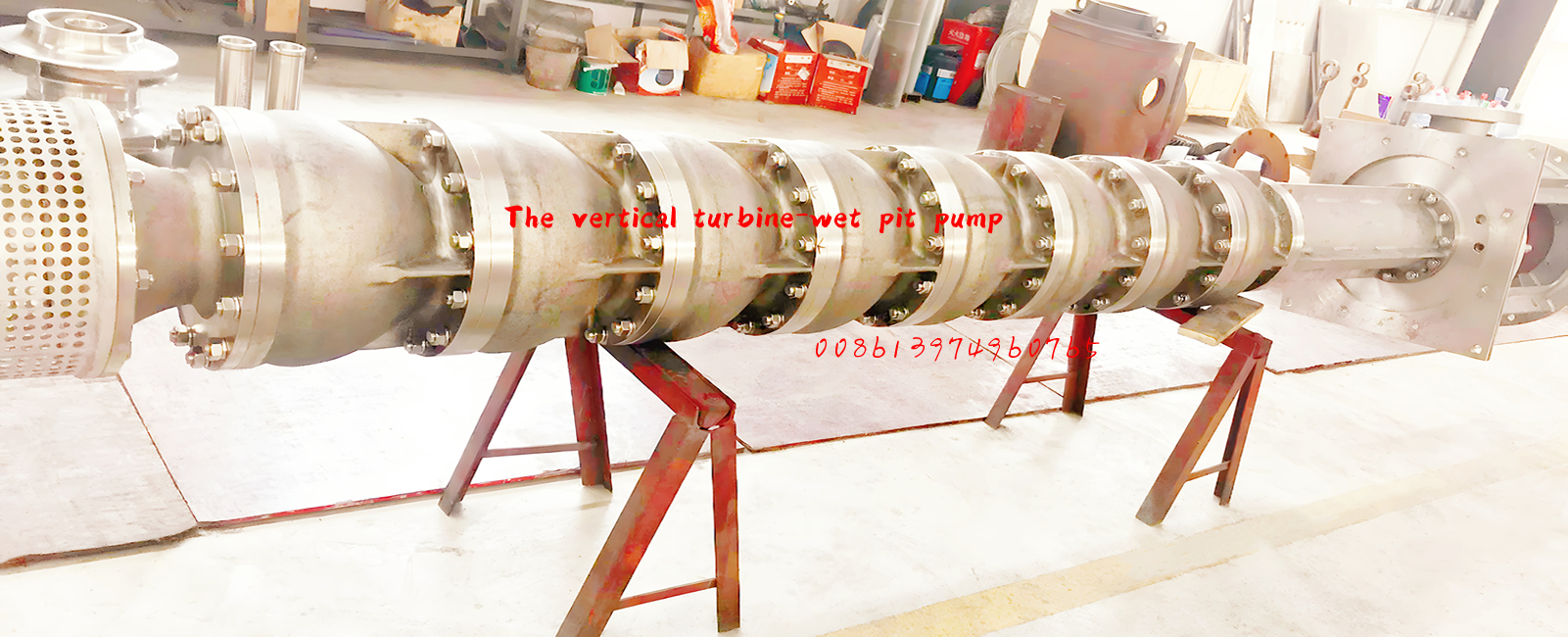
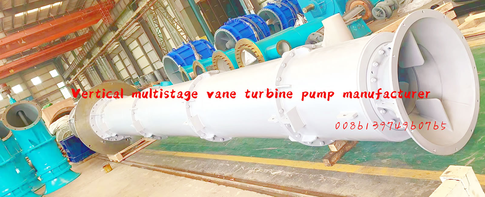
The body of the axial flow pump is composed of a water inlet horn, an impeller, a guide vane, a water elbow, a shaft, and a bearing. Packing seals and other compositions, see figure. The pump shaft is borrowed at both ends
The lower two are supported by water-lubricated rubber bearings, and the surface of the journal is plated with hard chrome.
A set of nuts are set at both ends of the pump shaft, which are fixed with the hub body and coupling respectively. When the pump is running, the axial force is absorbed by the thrust bearings in the transmission.
The axial displacement of the pump rotor is adjusted by a round nut in the transmission.
The axial force of the pump, the weight of the transmission device and the motor, and the weight of the rotor are all borne by the floor foundation supporting the transmission device. The weight of the casing of the pump is based on the pump
Withstand.
An intermediate transmission shaft is set between the vertical motor and the water pump, and the motor end of the transmission shaft is an elastic coupling, and the pump end is a rigid coupling. Motor mounting height L
It is determined by the user and the manufacturer.
The length of the transmission shaft is generally used within the "L" size range specified in the installation outline drawing, and if it exceeds the specified size, it is necessary to set up an intermediate bearing.
The outlet channel of the axial flow pump generally adopts a straight cone diffusion outlet pipe, and the end is equipped with an outlet valve.
The impeller is tested for static balance.
The gap between the hub body and the guide vane body is 0.5-0.6% of the diameter of the pump outlet.
For the cylindrical impeller chamber, it is cast into one with the water inlet horn, and the blade placement angle is installed in place at one time according to the user's requirements, and the user shall not change it at will.
The gap between the outer edge of the impeller and the impeller chamber is about 0.1% of the impeller diameter, and the gap should be appropriately increased when the conveying medium is sewage and impurities.
Steering: Looking down from the direction of the motor, the pump rotates in a clockwise direction.
2. Single basic structure with direct connection between motor and pump
This type of pump is directly connected to the motor through the motor support, and the pump outlet can be designed above or below the base layer according to the engineering requirements.
The axial water thrust becomes the internal force of the unit and is not transmitted to the foundation, which greatly reduces the design strength requirements of the foundation load.
This model is installed, centering and maintenance is very convenient, and there is no intermediate drive shaft.
Pumps can be designed as rotor component extraction or as integral extraction.
The pump shaft can be designed with a protective tube to protect it, and the sliding bearings can be lubricated and cooled with clean water to adapt to the working conditions of the medium containing particles.
The pump inlet flow channel can adopt an oval inlet flow channel to improve the cavitation resistance and device.

